Flush or Non-Flush, Looks Can Be Deceiving

In almost all inductive proximity sensor applications the housing design and mounting method of the sensor need to be taken into consideration. Sensor housing designs have historically been described as shielded (sometimes called flush) or non-shielded (sometimes called non-flush). In reality the terms shielded and flush have different meanings just as non-shielded and non-flush have different meanings. By using these terms interchangeably some confusion is typically created. Additionally, a new term of “quasi-flush” has entered the market. Let’s take a closer look at these terms and what they really mean.
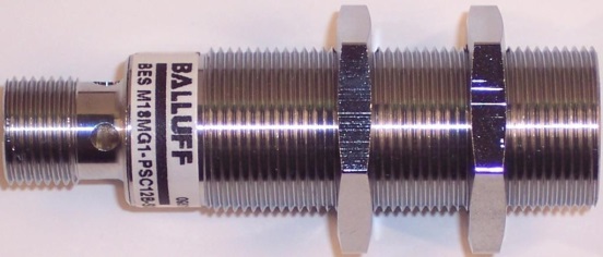
Shielded or Flush image
A “shielded” inductive sensor is a sensor in which the housing extends the full length of the sensor barrel – all the way to the sensor’s face.  The housing acts as a “shield” to restrict the sensor’s magnetic field so it only radiates out of the face of the sensor.   For standard sensing range models, these sensors can typically be mounted “flush” in metal without affecting their sensing distance.  The advantage this housing design offers is that it protects the sensor coil from physical damage and often provides longer sensor life in abusive applications.
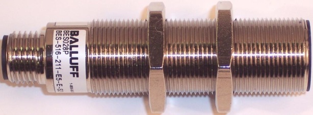
Non-shielded or Non-flush Image
A “non-shielded” inductive sensor is a sensor in-which the housing does not extend the full length of the sensor.  In most designs the first 5-10mm around the sensing face is actually a plastic cap encapsulating the sensor coil.  This allows the sensor’s magnetic field to extend farther out of the face of the sensor as well as out of the sides of the sensor “cap”.  The advantage this housing provides is that it creates a larger magnetic field and achieves a longer sensing range (1.5 to 2 times longer) versus a shielded sensor housing.  This larger magnetic field can also balloon down past the sensor housing.  For this reason this sensor must be mounted “non-flush” with the plastic cap of the sensor and typically a portion of the metal housing extended out of its metal mount or bracket.   If the sensor face is not mounted with this offset distance it can latch on immediately or false trigger in the application.  The offset distance needed will be supplied by the manufacturer. Make sure this offset distance is maintained during the installation process.
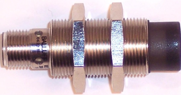
Quasi-shielded or Quasi-flush Image
A third and newer type of sensor housing available is sometimes called “quasi-shielded” or “quasi-flush”.  This term is used when referring to a sensor that has a “shielded” housing design, yet has to be mounted similar to a “non-shielded” model to achieve its full sensing range.  The sensor adjacent is a “quasi-shielded” sensor.  As you can see – looks can be deceiving.  This sensor looks like a normal “shielded” sensor but it is not.  In a “quasi-shielded” model the sensor electronics have been tuned to achieve 3 or 4 times the normal sensing range of a “shielded” sensor.  In many cases this is a great advantage as a smaller diameter sensor can be used in place of a larger one.   This sensor’s stronger magnetic field balloons down below the metal housing of the sensor and extends much farther out of the face of the sensor.  Typically this sensor CAN be mounted “flush”, but it will reduce the sensing distance achieved.  To obtain the rated sensing distance (3 or 4 times normal) the sensor face and housing must extend out of its mounting material by an offset distance.  The offset distance required for each sensor will be defined by the manufacturer and should be referenced before installation.
To avoid confusion, the main concepts to remember are that the terms shielded, non-shielded, and quasi-shielded refer to the housing design of the inductive proximity sensor.   The terms flush, non-flush and quasi-flush refer to the allowable mounting method of the sensor.  Looks can be deceiving so make sure you understand the sensor housing design and mounting requirements to avoid unwanted surprises during installation.
Select from Express Stock options, M8, M12, M18, M20, M30 

If you require a cylindrical sensor you can use the below sized links for threaded or smooth. Alternatively utilize the  Online sensor Selection Tool to configure a product code or, if you already have an existing sensor part code enquiry, please contact Sensemaster and we will provide a quote.

Threaded Cylindrical sizes
Smooth Cylindrical sizes